
Ads by Google

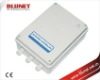
Control Panel
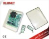
DIAGRAM OF THE SWITCHBOARD
Sliding Gate Operators
1 = Network filter protection
2 = Power supply transformer
3 = Radio module 434MHz frequency
4 = Connector for inclusion of CB-RF quarzate
radiofrequency board
5 = Adjustment of motor strength and deceleration
6 = Opto-insulated switchboard inputs with LED
display
7 = Programming via dip-switch
8 = Relay output for control of motors
9 = F1 NEUTRAL safety fuses power voltage
6.3A/250v AC
10 = F2 PHASE safety fuses power voltage
6.3A/250v AC
11 = Auto-reinstating fuse power voltage 24v AC
11 = Auto-reinstating fuse power voltage 12v AC
ELECTRICAL CONNECTIONS
CB-04Control Panel for AC or DC Automatic gate motor