

Ads by Google

HMIO1616 Manual
The main parameters:
Application:PLC IO expansion
Distributed Control System
Intelligent Building Control
Power Automation System
3..Dimension
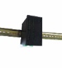
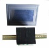
4.Installation
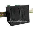
IO module for receiving external fault input signals and output control, the module provides 16 input 16 output signals IN and OUT. Module DIN rail mounting.
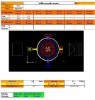
LED Indicators:
POWER: Flashes to indicate the Power is on;
COMM: Flashes to indicate the unit , when Communicating;
ERR: Error indication, when the something wrong, the red LED lighting;
IN01—IN16: Input indicator, "OFF" when the input is off. "ON" when the input is on;
OUT01—OUT16: Output indicator, the output is "ON" ,when the output is on.;
Warning!
Do not input 220VAC or 380VAC into the power connector, or the IO module will be burn.
In order to not Electric shock, please operate after turn off the power.
The outputs may be used to drive lamps or external relays when more drive capability is required. The outputs are isolated from the logic and they share a common negative terminal. The relay capacity is 220V3A.
Wiring:
1)wiring of the power:
Use isolated power supplies to ensure that the IO modules are not earthed.
Connect 24VDC – to 39, and 24VDC + to point 41.
2)Wiring of input
The following diagram shows how the digital inputs are connected to potential free switches. The common can be connected to positive or negative as indicated.
3) Wiring of output
The output can be used with 24VDC or 220VAC.
Control the load directly
Control the big load with Indirectly
4)wiring of the RS485 communications
Connect RS485 (+)A to point 42, and RS485 (-)B to point 43.
Note: Use RS485 shielded twisted cable to prevent electrical noise pickup, The RS485 line should have external over voltage protection to protect from high voltage electrical noise being induced into the RS485 cable. RS485 line is shorter then100 meters, if it is beyond 100 meters, please connect a 120 ohm resistor on the remote end.
5. The terminal
6. MODBUS-RTU Communications
6.1 Communications interface
RS485 Communications parameter:
BAUD RATE 9600, 19200 (normal 9600)
DATA BITS 8
PARITY None, Even, Odd (normal None)
STOP BITS 1, 2 (normal 2)
6.2 Communications distance
RS485≤ 1200m
6.3 Communications form
6.3.1 Read Input Status
04 code, specifies
Address+04+ 00+ 01+00+01+crc (word)
Response:
Address+04+02+00(Ho) +00 (Lo) +crc (word)
Data bits format:
Ho means high 8–bit , it is Input1 to Input8
For example: If input1 is On, 0000 0001 0000 0000
Lo means low 8–bit, it is Input9 to Input16
For example: If input9 is On, 0000 0000 0000 0001
6.3.2 Setting the Output Status
0F code specifies:
Address+0F+ 00+01 + 00+10+02+HStatus +Lstatus +crc (word)
Address is the device address,
0F+ 00+01 +00+10+02 is 0F code Fixed format,
HStatus + Lstatus: the output status,
With two bytes, high first, low in the post,
For example:
Set the Output1 on:
Binary: 00000000 00000001,converting to hexadecimal:00 01, It means the Output1 is On.
crc(word) is check code
Response:
Address+ 0F+ 00+01+00+10+ crc(word)
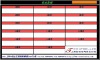
7 MODBUS terminal address
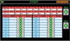
IO module Application in Distributed Control System