

Ads by Google

Performance Characteristics
1.Full CPU control the machine work, LCD displays the parameters, such as supply voltage. Control downlink input optical power, attenuation, equilibrium, uplink output optical power and laser current etc. variables, operation is convenient and intuitive, and performance is stable. Reduce a large number of optional accessories.
2.Excellent AGC characteristic, when the input optical power range is -9~+2dBm, the output level, CTB and CSO basically unchanged.
3.Optimizing circuit design, SMT production process, optimizing the whole signal path, made the photoelectronic signal transmit more stable, RF linear index higher.
4.Professional RF electrical adjustable attenuation chip, RF electrical adjustable equilibrium circuit, good linearity, high precision.
5.GaAs amplifier device, power doubler output, high gain and low distortion.
6.The return path adopts professional RF electrical adjustable attenuation chip instead of the three-state switch.
7.Reserved the data communication interface, can connect the Ⅱ network management responder, access to the network management system, the variables can be remote controlled by the network management.
8.The shell adopts embedded modular design; equipment maintenance, replacement, and debugging are convenient.
Performance parametersItem | Unit | Performance Parameters | |
WR1002JL-CEAM | |||
Forward Optical Receive Part | |||
Optical Parameters | |||
Receive Optical Power | dBm | -9 ~ +2 | |
Suggested Use Range | dBm | -3 ~ +1 | |
Optical Return Loss | dB | > 45 | |
Optical Receive Wavelength | nm | 1100 ~ 1600 | |
Optical Connector Type | FC/APC, SC/APC (or specified by the user) | ||
Optical Fiber Type | Single Mode | ||
Link Performance | |||
C/N | dB | ≥ 51 receive optical power(-1 dBm) | |
C/CTB | dB | ≥ 68 | |
C/CSO | dB | ≥ 65 | |
RF Parameters | |||
Frequency Range | MHz | 45/87~862(1003) | |
Flatness in Band | dB | ±0.75 | |
Rated Output Level | dBμV | ≥ 108 | |
Max Output Level | dBμV | ≥ 112 | |
Output Return Loss | dB | ≥16 | |
Output Impedance | Ω | 75 | |
Reverse Optical Transmit Part | |||
Optical Parameters | |||
Optical Transmit Wavelength | nm | 1310±10, 1550±10 or specified by the user | |
Laser Type | DFB or FP laser | ||
Output Optical Power | mW | 0.5, 1, 2 | |
Optical Connector Type | SC/APC (or specified by the user) | ||
RF Parameters | |||
Frequency Range | MHz | 5 ~ 30/65 (or specified by the user) | |
Flatness in Band | dB | ±0.75 | |
Input Level | dBμV | 75~85 | |
Input Return Loss | dB | ≥ 16 | |
Output Impedance | Ω | 75 | |
NPR dynamic range | dB | ≥15(NPR≥30 dB) Use DFB laser | ≥10(NPR≥30 dB) Use FP laser |
General Performance | ||
Power Voltage | V | A:AC 135~250 V/50Hz ; B:AC35~90V/50Hz |
Operation Temperature | °C | -30~+70 |
Storage Temperature | °C | -30~+70 |
Relative Humidity | % | Max 95% non-condensing |
Consumption | W | ≤70 |
Dimension | mm | 290(L)X210(W)X 155(H) |
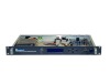
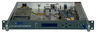
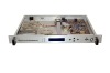
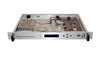
1. Signal input of forward RF module | 2. LED display screen | 3. Mode key |
4. Variable increase key | 5. Variable decrease key | 6. Reverse signal output |
7. AC 60V input | 8. AC 60V input voltage switch | 9. Module data acquisition and power supply interface |
10. Input total equalizer of reverse signal | 11. Input total attenuator of reverse signal | 12. Reverse low pass filter |
13. RF output 1 feeder switch | 14. Channel 1 forward RF signal output test port | 15. Channel 1 forward RF signal output (channel 1 reverse RF signal input) |
16. Channel 1 reverse RF signal input attenuator | 17. Channel 1 reverse RF signal input test port | 18. Channel 2 forward RF signal output (channel 2 reverse RF signal input) |
19. Channel 2 reverse RF signal input attenuator | 20. Channel 2 forward RF signal output test port | 21. RF output 2 feeder switch |
22. Channel 2 reverse RF signal input test port | 23. Module data acquisition and power supply interface | 24. Reverse signal input interface |
25. Reverse output optical power monitor port | 26. Reverse laser current monitor port | 27. Reverse laser optical power output state display (normal) |
28. Reverse laser optical power output state display (warning) | 29. Forward optical modules | 30. Reverse optical modules |
31. Laser drive level monitor port | 32. Forward RF module signal output interface | 33. Transponder RJ45 interface |
34. Transponder module | 35. Reverse optical signal connector interface | 36. Forward optical signal connector interface |
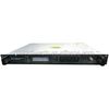
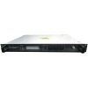
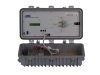
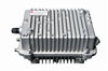
1GHz Bi-directional Modular Optical Workstation(WR1002JL-CEAM)