


Ads by Google

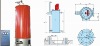
Energy plant will supply flue gas to the dryer directly. At the same time, it also provides heat as the thermal oil directly, and utilizing on thermal oil to produce steam for the refiner.
Flue gas ................................................................................... Flash tube Dryer Thermal oil .......................................................................................... Hot press .
Steam .................................................................. Refiner, press & resin making
The proposed energy plant comprised mainly of the following items:
a. Lower furnace designed with reciprocating grate, fuel feeding system and deashing system.
b. Upper furnace designed for dust burning.
c. Thermal oil heater and primary loops(pumps and connection fittings).
d. Deashing system and dust collection system for flue gas.
e. Steam boiler and soft water system f. Control system with HMI Reciprocating Grate
Main equipments;
Fuel storage and preparation system
In order to avoid unscheduled shutdowns of the energy system, the design of the fuel storage and feeding system is necessary for saving wood waste. The moving bottom fuel bin consists of 4 groups of pusher, each group with 2 beams and a center flight. In accordance with user’s requirement, the system could also be programmed to store the wet and dry fuel separately; to feed as per predefined ratio; and to perform uniform mixing to ensure stability of the energy system. The hydraulic system for the moving floor fuel bin must also be conservatively sized to accommodate for variations in fuel type and density. The big diameter cylinders (Φ200-250mm) assure reliability in the hydraulic system by preventing breakage that usually plagues cylinders of smaller diameter.
Fuel feeding system
The pre-mixed fuel is then being transferred from the moving-floor fuel bin and fuel conveyor into the fuel feed hopper located in front of the furnace. On the top of the fuel feed hopper there is a flap gate whereas the bottom is water jacketed. A certain level of fuel level could ensure stability of fuel supply and at the meantime preventing back firing from the combustion chamber. The purpose of the water jacketed is to protect the facility from damages in case of accidental back firing. The fuel feeding system is comprised of fuel level control sensors, cooling water, temperature sensor, and water spray nozzles. The fuels are extruded into the furnace by 4 hydraulic driven feeders. The fuels are then spread evenly on the width of the grate.
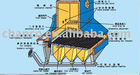
Reciprocating grate and combustion chamber
The wood waste is burned in a combustion chamber designed with a reciprocating grate system. The combustion chamber consists of steel casing lined with refractory materials and insulation materials. Burning waste wood for larger firing capacities at low emissions rates demands a reciprocating grate in order to get continuous operation, stable and easily adjustable combustion results and fully automated deashing system. The reciprocating grate distributes the fuel well over the whole grate area and simultaneously moves the ash and slag away from the firing area into the deashing conveyor. The reciprocating grate is specially designed to burn high moisture content fuels because the grate speeds can be adjusted to vary the fuel bed height depending on moisture content.
The fuel is fed into the grate area by hydraulic stoker feeders. The fuel pile height on the grate and combustion can be monitored and controlled at any time. The ash and slag is collected in a submerged ash conveyor placed beneath the grate. The fly-ash collected from the multi-cyclones can also be fed to this conveyor. All the wet ash is dropped in a bin from where a front loader can pick it up and move it to a dumping place. Wood waste is generally regarded as being very easy to burn. It is true that the heat value may vary considerably but the ash content is usually low and the ash melting temperature is normally high.
Mixing Chamber
This is where the flue gases from the heaters and furnace are mixed and discharged to the dryer blend chamber (Feeding Dryers) at much constant temperature. The mixing chamber administers to complete combustion of particles and in effect of further deashing capability
Emergency Stack
The emergency stack is mounted directly on the top of the furnace. The purpose of the stack is to vent the hot gases at emergency situations such as too high temperature or no underpressure in the combustion chamber, or in case of power failure.
Thermal oil heater
The thermal fluid heater consists of radiation and convection section. The radiation section consists of one large helical coil, the convection section of serpentine coils. An automatic soot blowing system (soot blowers) is included in the scope of supply. The radiation and convection sections are connected by a refractory lined transition duct which also makes up the supporting structure for all heater parts. A hood on top of the radiation heater makes the inlet duct for the flue gases coming from the combustion chamber. The flue gases are pulled through the heater by a heater Induced Draft (I.D.) fan, placed after the convection section. After passing through the heater, flue gases are cooled down to about 350°C. Multi-cyclone is placed between the I.D. fan and the convection section for deashing purposes as well as to protect the impellers from wearing out.
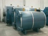
Steam boiler
The steam boiler is designed with three drums, nature circulation, membrane water tube shell and thickening pipe. Flue gas goes through boiler directly with no died corner. Automatic soot blowers are designed to avoid ash blocking. Big drum design can get high quality steam and good for the stable running.
Control system
The control system is the most important part of an energy plant. It controls the speed and precision of the system under different operating conditions. The control system mainly adopts latest computer and programmable logic controller (PLC) technology. By having programmed the software and HMI (visualization), it controls the motor control centre (MCC), frequency convertor, and PLC’s linked apparatus such as electrical motors and regulating valves. It carries out system automation & modulation thereby fulfilling the user’s requirement on heat load.
The HMI is integrated with functions such as real time monitoring of the energy system, checking operating conditions, modifying operating parameters, real time curving, historical trend, Proportional-Integral-Derivative (PID) regulation, system alarming, data logging, etc. The control system consists of mainly software and hardware:
Sensor and instruments
We use imported or renowned brand of sensor (temperature, pressure), switch, control valve, actuator, etc in the energy system.
Drivers, MCC, motor,MCC,
The main low voltage instruments are from Schneider product or other international renowned brands. The reliability of such drivers and equipments provide basic safeguard for the system.
PLC/PC systems
The control system is designed with SIEMENS S7-400 PLC with I/O components and host PC. The whole communication network for the control system is connected via Profi-bus and Fast Ethernet. Profi-bus DP communication technology is highly reliable and responsive for data transmission. Its strong anti-jamming property has effectively improved the precision of measure and control of the control system thus making it more reliable. Besides, it minimizes the use of system control cable (or even special cable) for the users thereby cutting down overall cost of installation as well as reducing maintenance workload
SIMATIC Step 7 program and Wincc Step 7 Wincc
The whole control system is programmed via SIMATIC programming software to give functions like data logging, logical control, PID regulations, safety joint and failure output, etc. The programming is done with clear structure through modularization of the control system. Having it programmed under Wincc, the HMI is integrated with functions such as snapshot screens, system alarming, real time curving, historical trend, PID regulations, data logging and access rights control. Access rights control enables the management to prevent disorderly control of a system by limiting the rights given to operators at different levels of seniority. Operators can only manage, control and modify operating parameters based on the rights assigned to each particular individual
energy plant