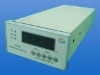
Speed Monitors
1. Display Range: 0.0001~99999
2. Input Signal Frequency: 1Hz ~ 10KHz
3. Weight: 1.0kg
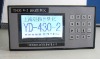
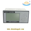
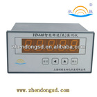
YD440 Speed Monitors 1. Brief Introduction: YD440 rotation speed monitor (microcomputer speed measurement instrument) is a rotational digital display indicator that applying single-chip microprocessor as the primary indicator. It’s five digits output display. This product can form a complete set with the rotation speed sensor that is output by square-wave, such as Hall, photoelectric and proximity switches or magnetic sine wave output speed sensor to measure rotation speed, liner speed, angular velocity etc. The display device can be widely used in chemical, metallurgy, energy, light industry, textiles, electronics, and machinery, automobile and other industries. Below is introduction for function , operation and other fields. Please read carefully before use to effectively use the indicator. 2. Main Technical Performance: Display Range: 0.0001~99999 (Decimal point can be set arbitrarily)Coefficient Setting Range: 0.0001~99999Input Signal Frequency: 1Hz ~ 10KHzInput Signal Amplitude: Sine Wave 0.3V~10V(Effective Value) Rectangular Wave 1V~5V(high level) 0V~1V(low level)Measurement Accuracy: 0.02 levelPower Supply: AC220V ± 15%, 50HzUse Environment: Temperature 0°C~40°C Relative Humidity ≤ 85% Atmospheric Pressure (86~106)kpa Dimensions: 160mm×80mm×130mm (Hole Size: 150mm×75mm)Weight: about 1.0kg 3. Operation Instructions: a. Before application, please connect the display device with power, it will show "00000" within 5 seconds and display the count. Reset display "xxxx0" after about 3 seconds the signal disappears.b. Parameter settings:1) "Set" key as a parameter shift key. Press "Settings" button; enter the set state, A, B, C, D, E will be displayed in sequence. First enter the A state, A and a single digit will flash. Then press "Settings" button to return to running status.2) "Confirm" is the confirmation key, it change the parameter under the status of re-setting. "∧" is button to add 1. Press "add to the above" on the setting value of the flash place , flash digital add 1; Under setting status, press "∧”key, setting parameters can be checked separately; press "confirm" key to set and change parameter, re-press "confirm" key , exit setting, Press "Setting" key to return to working condition.3) “”is the move to left key.Press“”key, unit, decade, hundred's place, kilobit, ten thousand place flash in sequence.4) The instrument including A, B, C, D, E five-speed parameters, A indicates the gear amount; B indicate the upper limit value of the measurement range; C indicate the lower limit value of the measurement range; D alarm upper limit value; E alarm lower limit value, enquiring user whether parameter has been set, if “" key pressed, then parameter setting finish and it will exit setting condition to enter working condition.5) “"Confirm”,"","∧”, with three key coordinate, every parameter gradually / tab set so as to achieve an arbitrary range of 0 to 99999 .6) Press "Reset" button back to the initial state of the set coefficient, re-enter the work state.c. Take an example to instruct the setup of the coefficient and parameter. Coefficient A factory setting be 60(gear), parameter B(lower limit value of the measurement range ) factory setting be 0, parameter C (upper limit value of measurement range ) factory setting be 1500, parameter D( alarm value of lower limit) factory setting be 750, parameter E ( alarm value of upper limit) factory setting be1500. Press "Settings" button, shown as A, press "confirm" key to enter setting, shown as 00000, single digit begin to flash, press "∧" to increase or decrease value,; press“”key to set the tens digit as 6, press "confirm" key to save after set up. Press "∧" button, shown as B, press "confirm" button to enter settings, set the parameters B as the way to set A. Press "∧" button, shown as C, press the "confirm" button to enter settings, set the parameters C as the way to set A. Press "∧" button, shown as D, press the "confirm" button to enter settings, set the parameters D as the way to set A. Press "∧" button, shown as E, press the "confirm" button to enter settings, set the parameters E as the way to set A. After setting all the parameters, press "Settings" button to return to working condition!d. Wiring (for reference)
| 1 | 2 | 3 | 4 | 5 | 6 | 7 | 8 | 9 | 10 | 11 | 12 |
| I+ I- Iout | J1(upper limit alarm) | J2(lower limit alarm) | RS232 |
| 12V S+ S- 0V S(A) S(T) | | 0V ~220V |
| 13 | 14 | 15 | 16 | 17 | 18 | 19 | 20 | 21 | 22 | 23 | 24 |
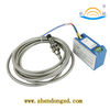
Note: While equip with YD60 magnetic speed sensor Wiring board S + Terminal connect sensor signal output side; The instrument attached with alarm output of upper/lower limit (J1 is upper limit alarm, J2 is lower limit alarm) The instrument attached with analog 4~20mA output.
YD440 Rotation Speed Monitors