


Ads by Google


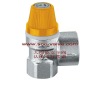
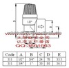
Yuhuan Tino Imp&Exp Co., Ltd is complex of producer and trading company , mainly producing kinds of safety valves, T61M seriese for electric water heater, T611-614 for wall-hung boiler and central heating system, 61T1-61T2 is designed for pressure vessel such as solar water heater, any steam tank ,which need control temperature and pressure.
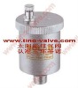
And Automatic air vent including solar air vent, home appliance water pressure reducing valve. And other brass fitting.
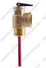
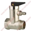
Defination:Temperature and Pressure (T&P) relief valves
Temperature and pressure (T&P) relief valves used on residential water heaters are typically designed and manufactured to relieve on pressure at 150 psig and on temperature at 210 degrees F. These ASME, ANSI and CSA (AGA) approved relief valves protect the water heater from excess pressures and temperatures by discharging water.
In normal operation of the water heater and T&P valve, no water should be discharged from the valve. A T&P valve that discharges is an indication of an abnormal condition in the system and by discharging, the T&P valve is meeting its designed safety purpose. The causes of discharge can be thermal expansion, excess system pressure, low temperature relief, too high a setting on the water heater, or something in the water heater causing excess temperatures in the heater.
Thermal Expansion: When water is heated it expands. In a 40 gallon water heater, water being heated to its thermostat setting will end up expanding by approximately 1/2 gallon. The extra volume created by this expansion has to go somewhere or pressure will dramatically increase, such as when water is heated in a closed system.
A good indication of thermal expansion is when the T&P valve releases about one cup of water for each 10 gallons of heater capacity with each heating cycle. The T&P valve is functioning properly when it relieves pressure caused by thermal expansion, but frequent relief can build up natural mineral deposits on the valve seat, rendering the valve inoperative. This condition can be addressed by the installation of a Watts thermal expansion tank or other Watts thermal expansion device to protect your system from overpressure caused by thermal expansion. If there is no discharge from the valve, there is no need to replace the valve.
System Pressure: If installation of a thermal expansion device does not relieve occasional dripping from the T&P valve, then the system pressure should be checked. If system pressure is excessive (typically more than 75 PSI), a Watts pressure regulator should be installed on the incoming water line.
Warning: The discharge from a T&P valve can be very hot. It is very important that all T&P valves be installed properly with a discharge line piped downward to an adequate drain to avoid property damage and to minimize possible human contact. Please read and follow the instructions on the warning tag attached to your T&P valve.
Correct Installation of T&P Relief ValvesImportant Instructions: Relief Valves and Automatic Gas Shut-Off Devices Combination temperature and pressure relief valves with extension thermostats must be installed so that the temperature-sensing element is immersed in the water within the top 6" (152mm) of the water storage tank. They must be installed either in the hot outlet service line or directly in a tank tapping. Combination temperature and pressure relief valves that do not have extension elements must be mounted directly in a tank tapping located within the top 6" (152mm) of the water storage tank. Valves must be located so as to assure isolation from flue gas heat or other ambient conditions that are not indicative of stored water temperature.
WARNING: To avoid water damage or scalding due to valve operation, discharge line must be connected to valve outlet and run to a safe place of disposal. Discharge line must be as short as possible and be the same size as the valve discharge connection throughout its entire length. Discharge line must pitch downward from the valve and terminate at least 6" (152mm) above a drain where any discharge will be clearly visible. The discharge line shall terminate plain, not threaded. Discharge line material must conform to local plumbing codes or ASME requirements. Excessive length over 30' (9.14m), or use of more than four elbows or reducing discharge line size will cause a restriction and reduce the discharge capacity of the valve.
No shut-off valve shall be installed between the relief valve and tank, or in the discharge line. Valve lever must be tripped at least once a year to ensure that waterways are clear. When manually operating lever, water will discharge through discharge line and precautions must be taken to avoid contact with hot water and to avoid water damage. This device is designed for emergency safety relief and shall not be used as an operating control. If discharge occurs, a licensed contractor must evaluate the system and determine the cause for discharge and correct the cause immediately.
To ensure proper operation, this valve must be installed by a qualified service technician or licensed plumbing contractor in accordance with these instructions and the local plumbing codes and standards. Repair or alteration of valve in any way is prohibited by national safety standards/local codes.
For Heaters with Direct Top Tapping:Always use an extension type thermostat T&P relief valve which permits the end of the thermostat to extend into the top 6" of the tank.
Direct Side Tapping:FOR EXTERNAL FLUE HEATERS: Use extra length extension thermostat to extend into water storage tank. FOR INTERNAL FLUE HEATERS: Use short or standard length thermostat. Vertical discharge line must be installed with its direction downward.
"Alternate" ONLY when the tappings are not provided:Use standard or extra length extension thermostat which permits the end of the thermostat to extend into the top 6" of the tank.
Important: A relief valve functions, in an emergency, by discharging water. Therefore it is essential that a discharge line be piped from the valve in order to carry the overflow to a safe place of disposal. The discharge line must be the same size as the valve outlet, and must pitch downward from the valve.
ANNUAL OPERATION OF T&P RELIEF VALVES:
WARNING: Following installation, the valve lever MUST be operated AT LEAST ONCE A YEAR by the water heater owner to ensure that waterways are clear. Certain naturally occurring mineral deposits may adhere to the valve, blocking waterways, rendering it inoperative. When the lever is operated, hot water will discharge if the waterways are clear. PRECAUTIONS MUST BE TAKEN TO AVOID PERSONAL INJURY FROM CONTACT WITH HOT WATER AND TO AVOID PROPERTY DAMAGE. Before operating lever, check to see that a discharge line is connected to this valve, directing the flow of hot water from the valve to a proper place of disposal. If no water flows when the lever is operated, replacement of the valve is required. TURN THE WATER HEATER “OFF” (see your water heater instruction manual) AND CALL A PLUMBER IMMEDIATELY.
REINSPECTION OF T&P RELIEF VALVES:
WARNING: Temperature and Pressure Relief Valves should be inspected AT LEAST ONCE EVERY THREE YEARS, and replaced, if necessary, by a licensed plumbing contractor or qualified service technician, to ensure that the product has not been affected by corrosive water conditions and to ensure that the valve and discharge line have not been altered or tampered with illegally. Certain naturally occurring conditions may corrode the valve or its components over time, rendering the valve inoperative. Such conditions can only be detected if the valve and its components are physically removed and inspected. Do not attempt to conduct an inspection on your own. Contact your plumbing contractor for a reinspection to assure continuing safety. FAILURE TO REINSPECT THIS VALVE AS DIRECTED COULD RESULT IN UNSAFE TEMPERATURE OR PRESSURE BUILD-UP WHICH CAN RESULT IN SERIOUS INJURY OR DEATH AND/OR SEVERE PROPERTY DAMAGE.
If discharge occurs, CALL A PLUMBER IMMEDIATELY. Discharge may indicate that an unsafe temperature or pressure condition exists which requires immediate attention by a qualified service technician or licensed plumbing contractor.
TYPICAL INSTALLATION:
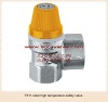
Caution: Valve must be installed so that temperature sensing element is immersed in the water within the top 6" (152mm) of the tank.No valve may be placed between the relief valve and water tank.Install in hot water outlet or in extra side relief valve tapping if one is provided.To avoid water damage, discharge line must be run to a safe place of disposal and must pitch downward.Do not install a shut-off valve, plug, or cap in the valve discharge line.Follow local codes where they vary from these instructions. Quality control:solar temperature and pressure relief valve