

Ads by Google

RATED POWER | 500W |
MAX POWER | 700W |
OUTPUT DC VOLTAGE | 24V |
START WIND SPEED | 2.5m/s |
RATED WIND SPEED | 11m/s |
MAX WIND SPEED | 40m/s |
Cut-Out Wind Speed | None |
Blade Pitch Control | None, Fixed Pitch |
Overspeed Protection | Auto Furl |
Gearbox | None, Direct Drive |
Temperature Range | -40 to +60 Deg. C (-40 to +140 Deg. F) |
ROTOR Diameter | 2.50m |
Rotor speed | 400rpm |
blade | 3 |
Blade material | Reinforced fiber glass |
Height of tower | 6.0m |
Generator | 3 phase permanent magnet alternator |
Sine Inverter power output | AC 110/220V, 50HZ/60HZ |
Weight | 125 kg |
Packing for shipping | Three Cartons 70x44x32cm 300x20x22cm 140x20x15cm |
Battery Configurations | Battery Specifications: 12V/180AHMinimum Battery Quantity: 2pieces |
ystem Description
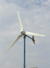
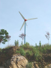
Wind Turbine System
Blades/Rotor System
The rotor system consists of three aluminum blades. Acting like aircraft wings, the blades convert the energy of the wind into rotational forces that can drive a generator. The aluminum blades are exceptionally strong . The rotor has three blades because three blades will run much smoother than rotors with two blades.
Alternator
The WPS-500W wind generator is a horizontal axis wind generator. The alternator utilizes permanent magnets and has an inverted configuration in that the outside housing (magnet can) rotates, while the internal windings and central shaft are stationary.
The output from the alternator is three-phase alternating current (ac), but it is rectified to direct current by the charge controller which is a part of the system. Since it uses permanent magnets, the alternator is generating voltage whenever the rotor is turning.
Nacelle
The nacelle is the aluminum housing around the main body of the machine. It contains the main structural backbone of the turbine (called the mainframe), assembly the yaw bearings, and the tower mount. The yaw bearings allow the wind turbine to freely pivot around the tope of the tower so that the rotor will face into the wind.
Charge Controller
The charge controller serves as the central connection point for the electrical components in the system and it provides 2 valuable control functions. It rectifies the AC output from the turbine into direct current (DC) and charge the battery. And it continually monitors the battery voltage and compares it to the regulation set point. The regulation set point is factory set to 28.2V (24V Turbine). When the battery voltage rises above the set point, it automatically stops charging the battery. It will wait for the battery voltage to drop. Normal charging will resume when the battery voltage drops slightly below the fully charge level. For 24 V turbine the controller will resume charging at 22V.
Tower Kit (optional)
The WPS-500W is offered with the guyed tubular tilt tower. For installation procedures on this tower please refer to the manual of 6m LAND TOWER KIT
System Operation
Normal Operation
The rotor of the FD500W should begin to rotate when the wind speed reaches approximately 3m/s. (for the first several weeks of operation, however, the start-up wind speed will be higher because the bearing seals have not worn in) battery charging should commence shortly after the rotor spins up to speed. Once turning, the rotor will continue to turn in lower wind speeds, down to approximately 2.5m/s. the rotor speed will increase with increasing wind speed and the system will provide a higher output. This output increase rapidly because the energy available in the wind varies as the third power (cube) of the wind speed. For example, if the wind speed doubles from 5m/s to 10m/s, the energy in the wind increases by a factor of eight(2 3=2x2x2=8). One result of this relationship is that there is very little energy available in light winds. For the average site, winds in the range of 5.5 -12m/s will provide most of the system annual energy production.
High Winds – AutoFurl
During periods of high wind speeds the AutoFurl system will automatically protect the wind turbine. When furled, the power output of the turbine will be significantly reduced. In winds between 13m/s and 18m/s it is normal for the turbine to repeatedly furl, unfurl and then furl again. In winds above 18m/s the turbine should remain continuously furled.
AutoFurl is a simple and elegant method of providing high wind speed protection. The AutoFurl system is based on aerodynamic forces on the rotor, gravity, and the carefully engineered geometry of the wind turbine. As shown in Figure, the aerodynamic forces acting on the blades cause a thrust force pushing back on the rotor. This force increases with increasing wind speeds. The thrust force acts through the centreline of the rotor, which is offset from the centreline of the tower pivot axis(yaw axis). Therefore, the thrust force on the rotor is always trying to push the rotor over to the side, away from the wind.
But the rotor is kept facing into the wind at speeds up to 12.5m /s by the wind turbine tail assembly. The tail, in turn, is kept straight by its own weight because its pivot at the back of the nacelle is inclined. So the weight of the tail holds it against a rubber bumper and the tail holds the rotor into the wind.
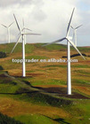
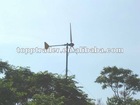
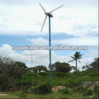
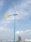
500W WIND TURBINE